Pedal Platforms and Stabilizer Forming

 The platforms for the Speedplay Frog pedals were coated on both sides with epoxy resin to seal the wood. After the resin had hardened, the excess resin needed to be removed in order for them to fit on the pedals. I used a Moto-tool with a flex shaft and a tiny cutting head to do this on the interior cavities, and the disc sander to remove the stuff along the edges.
 The next step was to apply a thin coating of resin to the top of the platforms and sprinkle some sand I scavenged from the backyard sandbox. I first toasted the sand with a propane torch to remove any organics, of which there was a bunch, as well as any moisture. Anyway, while applying the resin and then the sand I was careful to not get any on the threads of the T-nuts.
When the resin hardened the pedal platforms were put through the disc sander one more time, and the securing holes drilled again to permit the mounting bolts to pass through.
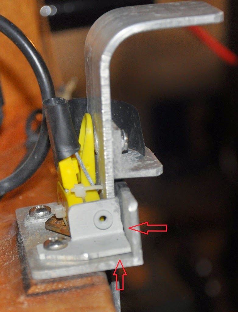
I ended up having to countersink the reverse side pedal mounting holes so the heads of the bolts would be flush. It didn't remove much of the plastic, so the strength of the pedal should not be compromised.

As can be seen in these photos, the platforms are flush with the pedal, and all the hardware is flush with the pedals as well. It remains to be seen how these platforms actually work in practice.

 The new stabilizer float halves were epoxied together. I used a bunch of Cadence propeller strut blanks and some blocks of steel that were laying about to provide pressure to eliminate any gaps, thus making for a better bond.
 To shape the stabilizers I decided to try a hot wire cutter. These seemed to be relatively simple to make and one ends up with a lot less styrofoam dust everywhere.
I read about how to make them from various web sites, and most suggest either using moderate gauge metal guitar strings or buying nichrome wire from Amazon or e-bay. Since I had a bunch of nichrome wire in the form of an electric heater with a frozen fan, I decided to scavenge it from there.


 The wire in the heater was coiled; I wanted it straight. So, after cutting a suitable length of the coiled wire I used a metal tube as a form against which I stretched the coil. The wire ended up pretty straight after making a number of passes over the tube while maintaining a good amount of tension on the wire. I guess I could have used a smaller diameter tube or possibly even a piece of wood and more tension to have a straighter wire, but I think this was good enough.
One novel suggestion for the hot wire setup was to use a PC ATX power supply's 12V outputs to drive the wire. As I happened to have a couple of these around I put one to use and tried it out. It was just about perfect. The wire did not turn red, but it was the right temperature to make a decent cut at a reasonable speed.

 One touch that I liked but probably didn't really help a whole lot was adding a spring and a turnbuckle to maintain tension on the wire. Since nichrome expands a lot when heating, I thought the spring would help. It turns out the setup has enough give in its structure that it probably isn't needed.
After testing the hot wire cutter on some scrap foam I was ready to cut the floats.

 First, I marked the curves of the sides using an old float as a template. I then pushed the foam block through the hot wire, perhaps a bit too quickly. Note the waviness of the sides. I think if the upper arm of the cutter was closer to the foam, and there was not so much of an overhang the results would have been quite a bit better from the start.
 After cutting both floats, I attacked them with the orbital sander. That managed to get them pretty close to what I wanted, though there were some low spots that will need to be filled before the outer skin of glass is applied.
 I then marked the curve of the underside of the bow, again using the old float for a template. I decided to have the angle go a bit higher at the front, and have the piece that was removed from the bottom placed on the top. This might help a little to prevent the diving plane scenario, as well as provide a little more flotation.
After sanding the bow with the orbital sander, which did a great job of smoothing things out, I used a hand sander to smooth the concave curve of the pieces that would soon be mounted on top of the bow section of the floats.

 After applying a layer of resin to the top of the floats at the front, the new top pieces were put in place. A number of weights were applied to try for a good bond.
The next step is to make the mounts for the floats. I'm planning to use both the grab tubes and the old float mounts on the boat to hold the same tubes as were used with the old floats. The distance between these two points is about 42.5 inches. Given the lack of precision in these two mounting points, I'll have to get the boat positioned so that the new floats are held in the correct place, and then install the mounts on the floats while the tubes are also in position on each side. It should be fun!
posted by Michael Lampi @ 6:40 PM
0 comments
![]()