All But the Final Clearcoat

Bits and pieces were completed during the week. With the successful testing of the T-nut I decided to use them to hold the prop strut bracket. However, due to the narrow taper of the stern, I bent the flange of one slightly so it wouldn't stick out when filleted in place close to the stern. The fillet material also refused to form a nice, smooth surface, so I figured that it would just get sanded with the Moto-tool once it hardened.

Additional sanding was done on the rudders, amas, stern deck and aka support areas. I removed the drips in the resin from the fore deck, too. Holes were drilled in the rudder control arms for the stretch and non-stretch cords. Afterwards, I applied a thin coat of resin to the recently glassed areas, and then thinned the remaining resin with lacquer thinner per the instructions of Vern Heikkala as well as the folks at System 3. The thinned resin had the viscosity of water, and was applied to all the sanded areas to give it one last glossy coating.

The prop strut bracket was made from a single U-channel of aluminum, 1 by 1 inch by 1/8 inch thickness. A slot was cut near one end to hold the strut, and holes drilled to align with the T-nuts just added to the stern deck.

I tried drilling another bushing for the coupler between the gearbox and the prop shaft, but this attempt was also unsuccessful. So, with shrink wrap plastic I tightly wrapped the end of the 0.625 inch diameter tube that was being used for the prop shaft and jammed it down the middle of a 3 inch long stainless tube that was chosen for a coupler that I had filled with fillet material. This actually worked fairly well.


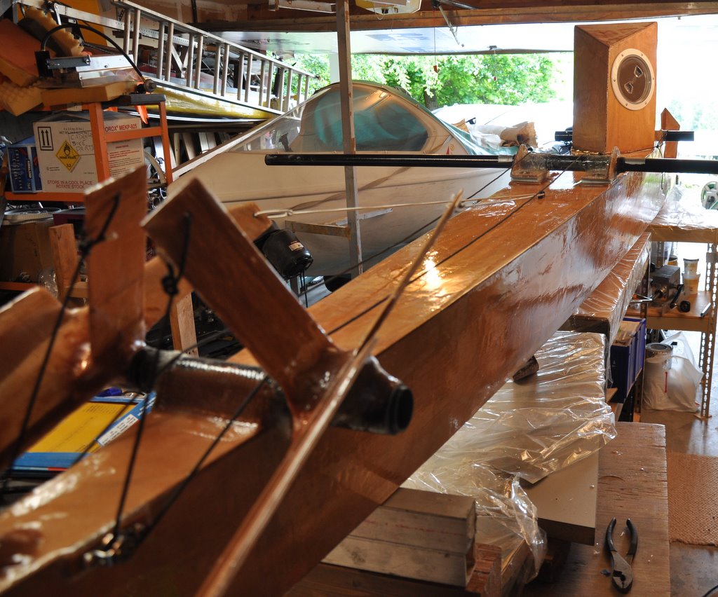


A couple of days later the next steps were to sand the excess resin from the rudders and the rudder bearings, and mount the cheeks (pulleys) on either side of the stern.
After running some tests with the lightest stretch cord I decided that using a single dead eye would be enough to pull down both rudders. There was too much friction to using the dead eyes as stretch cord guides, and I didn't want to add another pair of cheeks. Running the deployment cords over the top of the rudder bearing and over the top of the aka support removed the need to use dead eyes to guide them, too. There is a little friction to consider at the top of the rudder bearings, so it is possible the cord will wear. An application of resin there would help smooth things out.
I made loops at the ends of the cords so they would hang on the grab tube. The loops are long enough so that the rudders could be deployed fully and no more by merely pulling on the loop as far as it would go. Releasing the loop would allow the stretch cord to return the rudder to the stowed position.
Since I wanted the left side to also be able to control the right rudder I added a second control line with a knot at the end to distinguish it from the left rudder. It all seems to work well in the workshop.
The gearbox was mounted and bolted into place.
The aka supports were raised about 3/8 inch to be slightly higher than the tops of the large T-nuts. The space was filled with pieces of foam - at least until I figure out an alternative spacer.
Holes were drilled through the top of the aka support tube into the two akas. This is for the two 3/8" diameter push buttons that secure the akas to the aka support tube.
The amas were then mounted on the akas. Since they were mounted closer to their bows their sterns needed to be supported so the holes for the pins used to secure the amas to the akas could be drilled. I made sure to account for preloading the amas so they wouldn't drag their sterns while on the water.
I completed the propeller, too. The blades needed a bit of grinding at the hub so they would fit properly in the hub that Rick sent me. Once that was done everything went pretty smoothly. It was good I had a nice assortment of drill bits, including a size "W" bit to enlarge the bore to fit my almost but slightly larger than 3/8 inch diameter shaft.
The propeller was then mounted to the shaft, and the shaft connected to the gearbox via the coupler. I had to use the drill press to cut the holes. The hand held drill just didn't have adequate pressure to do the job.
A prop shaft strut was cut from a larger piece of 1/8" aluminum sheet. I cut it in the shape of an "L" so that overhang could be used in place of a bolt to retain the strut in the support bracket. The other end was essentially riveted to a plastic bushing that supported the propeller shaft.
So, with the exception of the final clear coat the boat is ready to go!
I really was hoping to launch this weekend, but with various family activities and having to search for quite some time for a couple of things that apparently fell to the bottom of a trash basket took their toll. I did get some weights, however:
Amas and akas: 6 pounds each set, 12 pounds total
Main hull: 35 pounds stern, 31.5 pounds bow, 66.5 pounds total
All up weight: 78.5 pounds
Note: The propeller shaft is at least 2 feet longer than it needs to be. I am going to see how badly it vibrates in practice as the joint between the tube and the rod are definitely not concentric. The extra length of rod+tube is about a pound, possibly more.
Sigh...this is only 15 to 20 pounds lighter than the carbon fiber Cadence (with outriggers) I used to have. While it is lighter than a standard Cadence without outriggers it is nowhere near where I wanted this boat to be; i.e., in the 50 to 60 pound range.
I think that using 4mm plywood is almost certainly overkill, especially if the more highly stressed areas are glassed on both sides.
Still, the resin coated wood makes for an absolutely gorgeous finish, and the material cost is considerably less.
We'll just have to see how well it performs.
posted by Michael Lampi @ 9:45 PM
0 comments
![]()

0 Comments:
Post a Comment
<< Home