Monday, February 28, 2011

Topside Taped

On a very chilly Saturday the top side of the boat was taped and sealed. Bits and pieces of cloth were draped over the cockpit at 45 degrees to the weave, measured and cut to fit. Other pieces were measured to cover the cockpit floor and seams. The edges of the wooden panels were rounded one last time with a sanding block to provide a couple of millimeters of radius to allow the cloth to follow surface. All dust and glass threads were vacuumed away.

The wooden fillets were checked for fit. One had to be sanded a bit at the end to fit against the deflector plate, which apparently moved somewhat forward when it was glued in place.

I started with applying resin to the top of the torque box first, followed by its sides and the cockpit floor. Using a cheap sponge brush I coated the wooden fillets on all sides and put them in place along the floor and the wooden bulkhead against the torque box.

The glass cloth was then laid on top of the fresh resin. Oops - not quite the right spot. Grr! Now it was shrinking in width, too!

Yes, the 45 degree cut allowed the cloth to stretch in length, which also caused it to shrink in width. Just lifting the cloth was enough to stretch it in length. The cloth had to be pulled wider and then applied to the sticky surface.

This repeated over and over. I figured that I'd be happy when I got to the rear deck where I had 90 degree strips prepared.

Anyway, it was taking a long time to get the cloth strips to nicely cover the seams of the cockpit area, and the cheap sponge brush was self destructing. Sigh...


Fortunately, my daughter arrived to provide assistance. I gave her a filter mask and rubber gloves and put her to work on the other side of the cockpit.

Working together we managed to get all the glass wetted out. My daughter progressed to gluing the deck seams and I finished up the cockpit.

At this point my daughter had other things to do so I bid her adieu and thanks for her help.

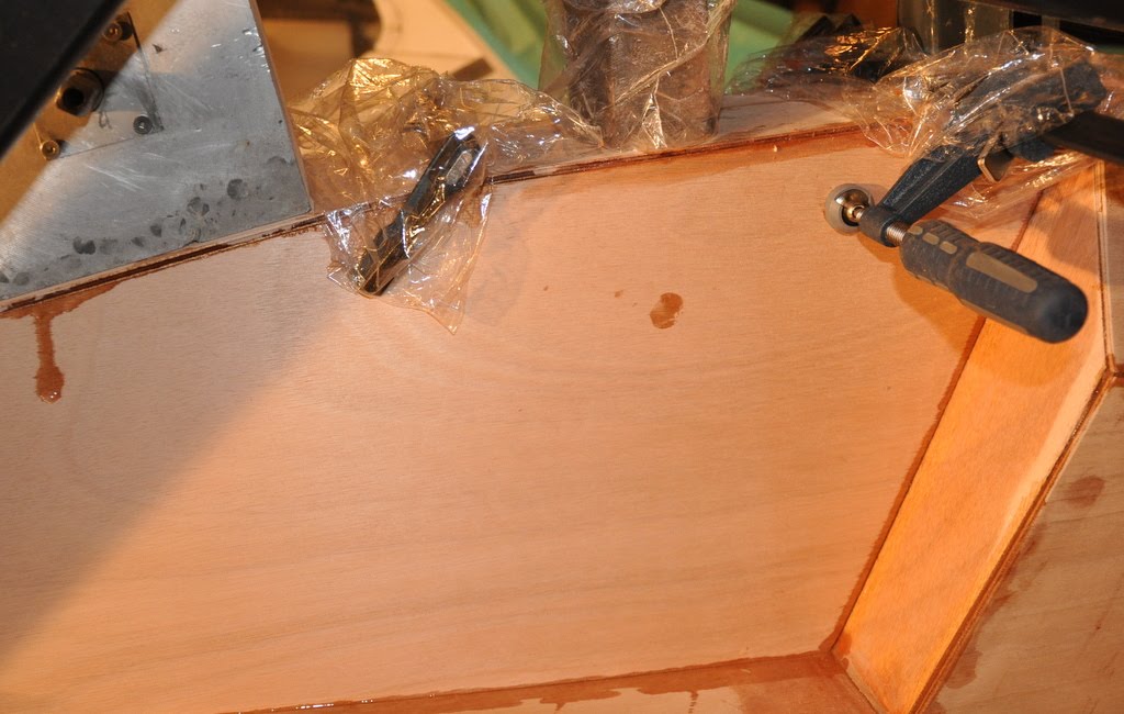
The rest of the front deck was covered in resin.

I took a piece of 12 oz 45 degree cloth, laid it flat on the plastic covered workbench and poured resin on it, letting it sit for a few minutes. The resin spread throughout the glass, saturating it nicely with no work on my part.

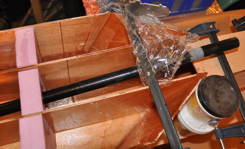
Picking it up carefully I then wrapped it around and over the bow.

Using shrink wrap plastic, pressed in place with foam rubber clamped between two boards, the glass was pressed against the wood hull. This was the same technique as used for the stabilizer bow and stern.

The next step was to tape and glass the rear deck. For this I had 90 degree cloth strips cut and applied. This seemed to work OK at first, but soon I noticed that the cloth was not staying flush against the surface near the edges. Rats! The edge was too sharp!

Just at this point my wife arrived and asked if she could help. Yes, certainly!

Giving her the roll of 6 oz tape I asked her to cut 4 to 5 inch strips of the cloth on a 45 degree bias. She took it to a warm part of the house, laid it on a large cutting table, and quickly cut it to size with a rotary cutter. This was much faster and cleaner cutting than with a scissors.

I removed the strips that I had placed on the rear deck, replacing them with the new bias cut pieces. Voila! The new pieces were much better behaved. Thank you, wife!

The stern was wrapped in 12 oz glass just like the bow, and also clamped in place.

The last step was to apply 6 oz cloth to the seat area. The piece was just a little too big, so short threads stuck over the edge. I think they will sand off fairly easily later.


The whole process took about 4-1/2 hours.

I'm now into the second gallon of resin.

Yes, the odor from the resin was what gave me headaches. With the very chilly weather (0 degrees C) we have been having I didn't want to open the garage door to ventilate. Instead, I used a wimpy exhaust fan I installed years ago that sucks air through a movable clothes dryer duct. Yes, it helped a bit, but after a while I decided to open the garage door anyway. It got pretty cold, and after a couple of hours of work the resin was not working quite as well - so I closed the door again. The resin is supposed to work down to 35 degrees with the fast hardener, so perhaps it reached that temperature.

I took off my work outer garments (thick cotton Army jacket, moderately thick jacket, thick inner cotton work shirt and shoes, and left the house after finishing the taping and took the family out to dinner, leaving the exhaust fan running all night.

Sunday morning I woke with a light version of the same headache as before. Yup - got to make sure there is adequate ventilation!

Friday, February 25, 2011

Seams Sanded


In preparation for taping the seams, I spent a couple of hours with the random orbital sander going over the seams on the hull. Rather than attempt to use fairing material to fillet the places where the deck overhung the sides of the hull, I sanded the edge of the deck back to the hull. This was no more than 1/8 inch or so in the worst sections, but it doesn't look too bad. The alternative would have been to fair in the hull to the deck. This would cover up the wood and generally look worse - unless the hull was painted. Fairing would also add to the weight, but holding the shape of the hull a little closer to the design might improve the performance a little.

Still, the sides of the hull and the bottom of the hull are generally in close agreement even if the sides didn't quite flare out as much as the deck. It should perform as designed.


I flipped the boat over for the first time and sanded down the resin drippings. It is just about ready for taping the seams!

The last thing I did was weigh the hull. According to my semi-accurate shipping scale the hull sans seat is about 36 pounds. Considering that fiberglass surf skis are in the 32 to 37 pound range, this isn't too bad. Of course, the boat will be much heavier once the seat back, gearbox, cranks, pedals, propeller, prop shaft, rudder and outriggers are added. Sigh....I'm hoping it will end up less than 60 pounds overall.

Adding cloth and more resin to the seams and bottom of the hull will add still more weight, too, but this is needed both for strength and for protection of the wood from scrapes and impact.

Monday, February 21, 2011

Rear Deck Glued

Sunday was going to be the day the rear deck was to be glued, but I woke up with a nasty headache that lasted most of the day. It might have been due to working in a garage with low VOC epoxy and minimal ventilation the previous day, and the activated charcoal filter might not have been enough to do the trick. Anyway, so far as work on the boat was concerned, all I did Sunday was to sand the still slightly green resin joints from Saturday in preparation for the future, when a layer of glass would be applied to the torque box and the top seam of the front deck.

Today (Monday) was President's Day here in the USA. It is a Federal holiday, meaning a bunch of folks get it off. My company doesn't have it as a holiday, but I took a day off anyway.

Removing all the weights form the torque box revealed a pretty nicely glued box. Some areas needed additional sanding, so that was done in preparation for the next step: gluing the rear deck.

Since this was the last time I'd have easy access to the stuffing box, I measured the angle of the 1 inch fiberglass pipe as it exited the hull, and at the end where it exited below where the seat bottom would be located. The two measurements were almost identical: 14 degrees and 13.5 degrees. Yes, there was a slight difference, but over the 64 inch length of the stuffing box this should probably be OK - I hope!

After opening the garage door for ventilation I mixed a cup of resin. Most of it was subsequently poured out along the length of the bottom side of the rear deck and squeegeed into the wood, turning it a nice even color.

I then used a 1 inch sponge brush to dab resin on the unsealed edges of the hull, from the seat back to the stern, on both sides. Resin was then applied to the back, sides and bottom of the stuffing box plate and to the roughened surface of the stuffing box. A weight was applied to the front end of the stuffing box as the stuffing box plate was mounted in place on the torque box.

More resin was applied to the top edges of the stuffing box walls where they became supports for the seat bottom.

Two teaspoons of fillet and one teaspoon of fillet hardener were mixed in another cup. This was applied generously around the interior wall of the stuffing box plate around the stuffing box as well as to the interior edges of its vertical joints.

More fillet was applied to the vertical convex edges of the diamond pieces securing the torque box. Fillet material was also placed on the tops of those pieces where they would join the rear deck to form the seat bottom.

With all the mating edges thus prepared, it was time to put the rear deck in position.

Lifting it carefully, it was flipped onto the boat, resin side down, with the front edge aligned with the stuffing box plate. Clamps were applied across the top to make sure that the edges were aligned with and would stay aligned with the sides of the hull.


Working back toward the stern, additional clamps were applied. Finally, at the stern, a clamp was used to make sure the deck and hull aligned properly. Another clamp was used to tighten the tip of the deck onto the hull.

Weights were applied along the length of the rear deck.

I spent a bit of time with paper towels wiping up resin drips and forming and removing excess fillet material in the cockpit area. Some of the excess material was applied to the top of the stern. The rest was applied to some gaps I noticed in the joints of the seat back and other areas.

As I had some excess resin, I decided to use it along with a piece of scrap plywood to help fill a gap in the seat back port side rear panel. This will make it easier to securely mount onto the deck when that time comes.

It is really getting to look like a boat!

Saturday, February 19, 2011

Torque Box Assembled

A couple of days went by and I decided to double check the measurements between where the output of the gearbox would be and where the propeller shaft would emerge from the stuffing box. Sure enough, though the gearbox output was parallel to the prop shaft it was about 3/16 inch too high. The sides of the torque box would need to be cut down a quarter inch to compensate. Back to the bandsaw!

Once the sides were cut I reassembled the torque box and placed weights on the top panel to try to bend it into the flattened S-shape. That seemed to work, though there was still a small gap at the lower curve. That should disappear if the weights are left in place for a couple of days.

Rick suggested reinforcing the area around the bottom of the hull where the fiberglass stuffing box exited the hull. Given that his hulls were glass and foam, and that this hull was plywood, it seemed to be adequate to add a second layer of plywood around the hole, some fillet material to fill the gaps and a layer of 12 oz cloth strips to cover the edges and the emerging stuffing box.

I thought of using the original plywood panel from the torque box as it had a hole ready made. Unfortunately, however, the hole was much too long as it was intended to intersect the stuffing box at a shallower angle. Still, the panel width was fine so I cut off the section with the hole and trimmed the remainder into a roughly 1 foot long tear drop oval.

A 1-inch hole saw was used to drill a hole near one end. The rest of the hole was rough cut with a coping saw and finished with a rasp. A couple of minutes on the belt sander shaped the outer edges with a 1/2 to 3/4 inch bevel.

I double checked the wood fillet pieces I previously cut to make sure they fit properly. The horizontal pieces were OK, but the two vertical pieces needed sanding to make a decent joint at their base and to taper nicely at the top.

Small drain holes were filed in the bottoms of the foam bulkheads in the torque box and below the seat. I don't want water to be trapped anywhere!

On Saturday I was ready to start gluing.

Several strips of 12 oz and 6 ounce glass were cut. The 12 oz glass was for the stuffing box. The 6 oz glass was for reinforcing the fore deck where it joined the hull.

A small cup of fillet material was mixed. This I applied to the gaps between the deck and the hull, to the depressions in the central fore deck joint, and to various gaps between other previously glued panels. A bunch was stuffed into the stern hull joint using a chop stick. This was intended to both strengthen the joint as well as to help reduce the chance of leaking after impact.

A cup of resin was mixed. The first area to which it was applied was the reinforcement plywood for the stuffing box hull entry and then to the inside of the hull where that piece was to go. I then inserted the stuffing box through the reinforcement piece and the hull to the proper depth, letting it hang unsupported at the long end. After adjusting the position of the reinforcement plywood I liberally applied the fillet material in the gaps and around the base of the stuffing box. The 12 oz cloth was applied around the stuffing box and the beveled edges of the reinforcement piece. A lot of resin was used to wet out the cloth.

Weights were applied to the reinforcement piece to get it to mate flush with the hull and to counter to torque of the unsupported stuffing box.

Later on, when the boat is flipped over to glass its bottom, the stuffing box will be filleted and glassed from the bottom side as well. Not today, though!

More resin was mixed and applied to the portion of the cockpit deck that would soon be gone from view. It was then applied to the inside surface and the top and bottom edges of the torque box side panels and the sides and bottoms of the foam bulkheads.

The side panels and foam bulkheads were then positioned in the cockpit area, making sure that forward edges were flush against the wooden bulkhead and centered.

The top panel of the torque box was next. Resin was applied to the two ends and to the bottom. Resin was also applied to the slanting foam piece that would sit below the gear box.

The top panel was then placed on top of the torque box, with the tabs of the aft end inserted between the two sides. Weight was applied here first, then to the middle section and finally to the forward end.

A clamp was applied at the top sides where the forward foam bulkhead supported the slanting foam piece.

Resin and foam were next applied to the deck/hull joint, and 6 oz glass strips applied to either side. Shrink wrap plastic and a spring clamp were used to flatten and secure the glass at the bow. Additional plastic was used to try to work out any air gaps between the resin impregnated cloth and the wood.

The last pieces to be glued in place were the two diamond shaped pieces that fit on either side of the torque box below the front seat. Resin was applied to the interior surface and the bottom and side edges only. After propping the pieces in place small strips of 6 oz glass were applied to the inside bottom joint and the interior hull joint. I'm not sure how much force will be applied to these pieces, but I plan to apply glass to the outer side and top joints later on.

A couple of hours later I went back to take a look to see how things were progressing. I was unhappy to see that some gaps had appeared at the top end of the "S" of the torque box top panel. Apparently not enough weight had been applied there.

I mixed a small batch of fillet material and removed the weight from that section, which caused it to start separating from the panels. Fillet material was liberally applied to the joint edges. Weights were then placed on this section, with double the amount previously applied. Excess fillet material was removed with a paper towel.

We'll see how this turns out tomorrow!

Saturday, February 12, 2011

Reworking the Cockpit

After taking a week off recovering from the Sound Rowers La Conner race, which I participated in my Escapade pedal boat (see http://soundrowers.org) and took photos of the event for the club, it was time to return to work.

The next stage in the building process is to put together the cockpit.

To do this, the following steps need to be taken:
1. Design the mount for the gearbox.
2. Modify the torque box to accommodate the gearbox and mount.
3. Clean up the edges of the torque box panels and underseat panels so they mate properly.
4. Add stringers to the rear hull to spread the sides to fit the rear deck.

Step 1: Design the mount for the gearbox
I had a number of grandiose ideas for how to mount the gearbox and make it adjustable. Some of these designs would require TIG welding, which is fine with me as I happen to do that as a hobby. On the other hand, if I could do this using off the shelf bits and pieces, then so much the better for anyone else who wants to do this on their own.

The design I ended up with is to use to simply use two flat panels of 1/8 inch thick aluminum that are bolted to either side of the torque box, with a series of 1/4" holes along the top edges in each panel. The gearbox is then bolted to a pair of right angle aluminum stock that extends an inch beyond the front and rear ends of the gearbox. Holes drilled in the extended section are aligned with the series of holes in the plates previously mentioned, and bolts are passed through securing the front and rear of the gearbox. Wing nuts or nylok nuts are used to hold the bolts in place.

Optionally, four very short bolts could be used if the two long bolts prove to be too loose in practice.

The weight of the gearbox is resting on the angle aluminum stock against the top of the torque box.

I'll take photos of this set up after I fabricate it.

Step 2: Modify the torque box to accommodate the gearbox and mount


Ok, now that the gearbox mount is designed, what modifications are needed to the cockpit to get it to align with the stuffing box?

As it turns out, the Involute gearbox is a pretty big beast. Measuring from where the seat back would be (2.85 meters, or 9 feet 4.20 inches from the stern) to where the center of the crank spindle is located (approximately 37 inches for my legs), the rear edge of the gearbox would be nearly an inch below the top of the torque box. Also, the stuffing box is too short for the top panel of the torque box.

The solution I chose was to trim about an inch from the torque box side panels starting just in front of the seat bottom, continue forward for about a foot, and then taper back to the original top edge at an angle parallel to the stuffing box. This would provide for a length of several inches longer than the Involute gearbox and allow it to be adjusted for shorter and longer legs.

I would have preferred to have left the gearbox up higher as this would have allowed for more heel clearance and possibly the use of standard length crank arms. Unfortunately, however, this would have caused the stuffing box to have emerged from the seat bottom rather than just below the seat bottom. The angle of the propeller shaft would have increased a bit, too, causing a bit more stress on the shaft.

After taking numerous measurements while seated in my Escapade, I decided that using shorter crank arms as on the Cadence would give me just enough clearance under normal circumstances. The stuffing box will stay at the original design angle.


By making the transitions gentle enough it was possible to bend a single piece of wood to comprise the top panel, simplifying construction and making for a nicer appearance.

The original top panel, though long enough to reach from the front bulkhead to the stuffing box panel, could not be used as it had a long oval hole cut in it for the stuffing box to emerge. So, using some of the scrap wood that was delivered along with the original panels, and the original top panel as a template, I cut a new torque box top panel.


While doing measurements and trial fits I noticed that the torque box side panels had a tendency to not want to stand perpendicular to the deck. This would only get worse when it was time to glue them, so I cut some foam bulkheads for under the seat and under the gearbox area. An additional piece of foam was positioned just under the top panel so the bolts securing the aluminum side panels for the gearbox mount would pass through it. This would help to keep the torque box from deforming under the pressure of the bolts and to help keep water out of the torque box.

Step 3. Clean up the edges of the torque box panels and underseat panels so they mate properly.

A small rectangular piece of wood was cut and drilled for the stuffing box panel mount. The sides were beveled to mate with the beveled edges of the torque box at the front of the seat bottom.

The rear end of the top panel of the torque box was notched at the corners so that it extended under the stuffing box panel mount by about 1/4 inch. I used a band saw to cut the notches and a flat file to adjust them to fit.

The two small, roughly diamond shaped panels were also beveled with a sanding block to fit on either side of the seat bottom.

The sides of the hull needed some filing in the area where the fillet material was present, and beveling with a sanding block to make a nice fit.

The front edges of the sides of the torque box also needed some touch up with the block sanded to get them to fit snugly against the front cockpit panel.

Step 4. Add stringers to the rear hull to spread the sides to fit the rear deck.

Since I plan to put the rear deck in place right after the cockpit is completed I double checked the fit of the sides of the hull with the deck. Near the stern I found that the hull was not spread apart enough at the deck, so I added a couple of small pieces of foam to spread the sides. This was also necessary near the seat back, as the sides had a tendency to push inwards.

I think that when the rear deck is glued in place I will use half a dozen or so clamps across the top. This is needed to make sure that the hull stays straight relative to the deck. However, in order to make sure the clamps don't inadvertently squeeze sides rather than align the deck with the sides, I'll use more right angle aluminum pieces inside the clamps. The pieces will be covered with shrink wrap plastic so they don't become a permanent part of the boat.

Labels: , , ,

Tuesday, February 01, 2011

Closing the Cockpit and the Fore Deck


A couple of hours here. A couple of hours there. Not much to look at but then suddenly there is a big change to the appearance of the boat. Progress is definitely being made!

After the hull was assembled and the resin set I went back to see how the deck pieces fit. The cockpit floorboard wasn't quite matching the upper edges of the hull, and the wooden bulkhead wasn't exactly meeting the edges of the hull, either. In fact, the starboard side of the hull at the floorboard was nearly 1/4 inch too far outboard, and the port side was about 4mm too far inboard. I hate it when that happens.

The solution was to take a hacksaw blade to the foam bulkhead near the starboard side and cut a long, thin 1/4 inch thick wedge from it, and insert a 4mm wedge on the port side of the same bulkhead. The application of some epoxy resin later on to these points could be done if I felt like it, but it really isn't necessary except to possibly stop squeaking when the hull flexes.

I had to do the port side on only one bulkhead, but three of the starboard bulkheads needed adjustment.

Since the floorboard didn't mate flush with the wooden bulkhead I sanded the edge that was too long until it fit reasonably well.

The next part to assemble was the fore deck.

Looking at the remaining panels I was still amused that there were three side panels for the fore deck when only two were needed. It is nice to have a spare, I guess.

The top center panel was designed to not quite fill the gap between the two side panels. According to Rick this was intentional as it is difficult to determine how it would fit given the thickness of the plywood and how it would fit after the pieces were beveled to mate. I don't know about that. It could easily have been 3 or four inches longer with no problems.

I took some fresh 80 grit sandpaper, made from the belt of my now-broken belt sander, and with the sanding block beveled the edges of the fore deck pieces. It didn't take much time at all. The sanding belt was quite durable and the grit stayed pretty sharp.

While checking the fit of the fore deck I found that keeping the pieces in place was a bit trying. The section of the hull between the 5m bulkhead and the bow needed to be spread a little at the top in order for the pieces to fit. So, another foam bulkhead was cut to fit at 5.5m.

With the new bulkhead things fit much better. Still, the top deck piece just would stay in place supported only by one edge. Something would need to be done to support it when the assembly phase commenced.

After some additional consideration I decided that the compartment just ahead of the wooden bulkhead and the one just behind where the stuffing box exits the hull would be ideal for storage compartments. They would serve double duty as access points for draining the hull should it leak. So, to make sure that water inside the various compartments could actually make it to these compartments I punched small holes at the bottoms of the foam bulkheads. By tipping the boat bow or stern up water could be directed to the compartments with the access hatches and removed.


Tonight I took a rectangular piece of scrap foam and traced the upper part of the wooden bulkhead on it. After cutting out the bulkhead shape I now had a cradle in which I placed the deck pieces upside down. Again, the markings in the wood were helpful in making sure the pieces were aligned properly.

Duct tape was used to hold the pieces together along the their curves, and to secure the top deck piece in place between the two side deck panels. Tape was also used to cover the gap between the end of the top piece and the side panels, as I intended to fill this area with fillet material.

With the panels mounted I measured and cut some 6 ounce cloth to cover the seams almost all the way to the bow.

All was ready for the next assembly phase.

I measured and mixed about 2/3 of a coffee cup of resin. It was spread thinly over the underside of the cockpit floorboard, the fore edge and the interior side edges where the floorboard enters the hull. The cuts in the bulkheads received some resin and their tops as well, along with the top edges of the hull. The floorboard was put in place and clamps and weights applied.

Fillet material was mixed and applied to the top and bottom interior side edges of the floorboard to as to provide some support below the seat area.

The deck panels were lifted from the cradle and placed flat on the bench. This allowed resin to be applied to the beveled edges as well as the interior surface. Once this was done the panels were placed back on the cradle and the pieces checked to make sure they were fitting properly together.

Fillet material was now applied to the interior seams and squeegeed smooth. The glass cloth was applied and the remaining resin was used to wet out the cloth. I had to mix up another small batch of resin as there wasn't quite enough of the old stuff left and it was beginning to set anyway.


While that was slowly setting I applied the remaining fillet material to the seam between the wooden bulkhead and floorboard, and to the vertical interior seam of the bow.

The remaining resin was applied to the edges of the hull from the wooden bulkhead to the bow, and to the edges of the deck currently sitting in the cradle.

Gently removing the deck from the cradle I set it in place on the hull and began tying it in place with shrink wrap plastic strips. This wasn't quite doing the job as gaps appeared in all the wrong places!
Grabbing a roll of duct tape I strapped the deck to the hull every couple of inches on both sides. This seemed to do the trick, and the pieces fit pretty well together.

There were a couple of sections of the hull that wanted to fit 2 or 3 mm inside the deck, however. Taking a thin piece of metal and using it to pry the hull outward did the trick and duct tape helped secure that as well.

I let this set overnight and upon returning from my day job I removed the weights and tape. Here are the results: